NBPhO 2023, Теория и експеримент — Задача 4. Black box
Nordic-Baltic Physics Olympiad 2023 · 12 т.
Условие
— Jaan Kalda, Eero Uustalu.
Tools: a black box with two output terminals, a multimeter, a stopwatch, wires.
The resistance of the multimeter is as follows: when used as microammeter — ; when used as a milliammeter — ; when used as a voltmeter — more than . When used as a voltmeter, the multimeter will automatically determine the optimum range, but this will slow it down; to make it faster, press the “Range” button to fix it to the current range.
Which four components (apart from the wires; there can be more than one of the same type) are in the black box? What are the values of the quantities that characterise these components and how could they be connected? Document and tabulate all your measurements and plot them graphically where appropriate.
Решение
— Solution by Jaan Kalda, grading schemes by ....
Since there can be elements causing inertia — chains or chains, one has to be patient when making measurements and wait for a long enough time to let the system relax towards an equilibrium. There are two types of measurements which can be done.
- After keeping the terminals short-circuited for a long enough time, release the short-circuting wire and measure the voltage as a function of time:
| (mV) | (s) | (mV) | (s) |
|---|---|---|---|
| 0 | 1073 | 90 | 2977 |
| 5 | 1317 | 100 | 3049 |
| 10 | 1564 | 110 | 3073 |
| 15 | 1765 | 120 | 3091 |
| 20 | 1950 | 130 | 3116 |
| 25 | 2109 | 149 | 3124 |
| 30 | 2248 | 159 | 3131 |
| 40 | 2465 | 160 | 3124 |
| 50 | 2629 | 170 | 3131 |
| 60 | 2751 | 180 | 3135 |
| 70 | 2850 | 210 | 3145 |
| 80 | 2921 | 400 | 3155 |
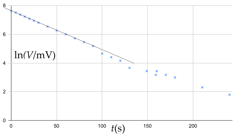
These data are plotted as versus time. One can see a fairly nice linear plot which means that voltage is approaching exponentially the limit value . The characteristic time can be found as the reciprocal of the trend line (we discard the rightmost data points as there, the voltage changes are small, so the relative errors are big), As a result we obtain .
- After keeping the terminals open for a long enough time, release the short-circuting wire and measure the current as a function of time:
| (μA) | (s) | (12.3 μA) | (s) |
|---|---|---|---|
| 0 | 978 | 50 | 351 |
| 5 | 794 | 60 | 345 |
| 10 | 636 | 70 | 341 |
| 15 | 535 | 80 | 340 |
| 20 | 468 | 90 | 339 |
| 25 | 425 | 100 | 339 |
| 30 | 397 | 110 | 339 |
| 40 | 365 | 120 | 339 |
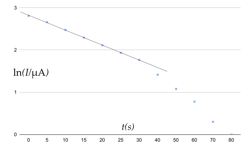
These data are plotted as versus time. One can see a fairly nice linear plot which means that voltage is approaching exponentially the limit value . The characteristic time can be found as the reciprocal of the trend line (we discard the rightmost data points as there, the voltage changes are small, so the relative errors are big), As a result we obtain s.
These data mean that inside, there should be a battery to maintain a voltage, a capacitor to provide inertia — exponential decay towards an equilibrium, and resistors. In principle, one should consider also an option where there is an inductor instead of the capacitor; however, it can be excluded by various ways. First, it is not realistic to obtain long enough relaxation times with an inductor. Indeed, already the internal resistance of the ammeter is around a hundred of ohms, and characteristic time of about 20 seconds would mean that the inductance should be around kilohenry — even if such inductor exists, it would not fit into the box. Second, if there were a big inductor inside, it cannot be a lone element connected to one of the terminals. Indeed, when the ammeter is connected to the terminals, a non-zero current appears immediately, instead of starting from zero (what would be the case if there were an inductor). So, it must form a closed loop with a resistor and a battery. However, in that case, if we keep the terminals short-circuited for a while and then disconnect, the voltage at the terminals would jump discontinuosly as the current through one of the resistors would need to jump (to keep the inductor current continuous).
The first consideration is that there need to be two resistors because there are two different characteristic times (one resistor with two capacitors can produce still only one characteristic time, because the capacitors, either in parallel or in series, would combine effectively into one single capacitor). Next, the restriction (I): the battery and the capacitor cannot be in series, because they would combine effectively into a single capacitor. Second, the restriction (II): the battery and the capacitor cannot be in parallel, either, because they would combine effectively into a single battery. Then, restriction (III): neither capacitor nor battery can be connected directly to the output terminals as in one case, the ammeter current would asymptotically approach zero when connected to the output, and in the other case, the output voltage would be always constant. This excludes automatically many possibilities, see below. Also, (IV): there should not be a direct path from one terminal to the other going only through the capacitor and the battery as in that case, ammeter current would be very big, and the corresponding characteristic time would be very short. Finally, (V): the capacitor can be only in a parallel connection with something, because otherwise, there would be no capacitor current when a voltmeter is connected to the output, hence, the voltage would remain constant.
Topologically, there are options (a) all in parallel — excluded by (I); (b) all in series — excluded by (II); (c) three elements in parallel, all together in series with the fourth element — excluded by (I) and (IV); (d) 3+1 parallel chains (i.e. 3 elements in one chain, and 1 element in the other chain) — excluded by (III) and (I); (d) one parallel pair in series with another parallel pair — excluded by (IV) and (II); (e) 2+2 parallel chains; (f) 1+2 parallel chains, all together in series with the fourth element; (g) a pair in parallel, all together in series with the third and fourth element.
With the option (e), battery and capacitor need to be in different chains, due to (I), this is the circuit A.
With the option (g), capacitor must be in the parallel pair with a resistor, due to (V) and (II), this is the circuit B.
With the option (f), due to (V), the capacitor needs to be in the parallel section, either (f1) as a single element, or (f2) paired in series with a resistor, because of (I). In the case of (f1), (III) tells us that battery must be in the other parallel section (in series with a resistor), this is the circuit C. In the case of (f2), combinatorics tells us that there are two positions for the battery — either as the single element in series which is the circuit (D), or in parallel with the capacitor-resistor series connection. The latter option, however, means that the battery would always maintain the same voltage on the capacitor-resistor series connection, i.e. the output voltage and current would remain always constant.
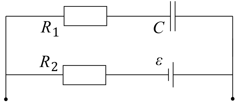
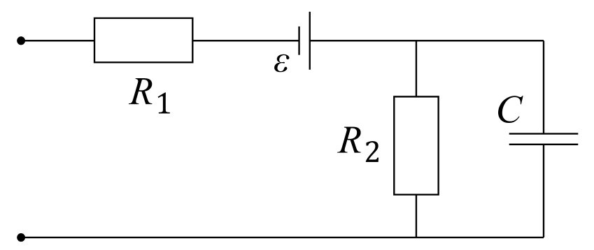
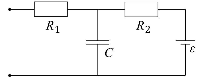
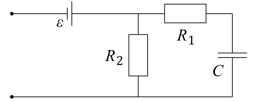
In all four cases, the voltmeter reading, when connected to the output, tends asymptotically towards the electromotive force of the battery, so .
For cases (A) and (D), the initial ammeter reading is and the asymptotic ammeter reading is ; based on that we can calculate and . For those cases, the initial voltage , so we can check if everything fits: we obtained , and ; this is a fit within the uncertainties.
For the very same cases, so that . Alternatively we can calculate the same thing using , hence . Again, there is a match of results within the uncertainties.
Finally, for (B) and (C), the initial ammeter reading is and the asymptotic ammeter reading is ; based on that we can calculate and . The expression for the initial voltage remains unchanged, , so we can again check if everything fits: we obtained , and ; this is a fit within the uncertainties.
Now, so that . Alternatively we can calculate the same thing using , hence . Again, there is a match of results within the uncertainties.
Grading:
Black box circuit diagram is correct:
- The initial voltage , which means that the circuit contains battery of some sort (0.5 pts)
- The changing current suggests that the circuit contains a capacitor or an inductor (0.3 pts)
- The use of an inductor is unrealistic for the provided black box, consequently the circuit must contain a capacitor (0.2 pts)
- The discharging of the capacitor is not instantaneous, so there must be a resistor between the capacitor and output terminals (1 pts)
- The recharging of the capacitor is not instantaneous, so must be a resistor between the capacitor and the battery (1 pts)
- Correct circuit diagram is drawn (2 pts)
- Additional notice: if the suggested circuit is such that one element would be masked by another element (e.g. a capacitor is parallel to a battery in which case the capacitor would be always fully charged and undetectable, or a capacitor is series with a battery in which case the battery voltage would be compensated by the capacitor and undetectable), the marks for circuit will be reduced by 50%.
Electromotive force of the battery is found correctly based on the drawn circuit diagram (1 pts)
The resistance of both resistor is found correctly (circuit diagram dependent):
- When the capacitor is fully charged the current doesn’t flow through it, or in other words ; either sum of two resistances or resistance of one of the resistors can be found (1 pts)
- Otherwise, when the capacitor is discharged in the first moments after the recharging has begun; either resistance of one of the resistors can be found or the equation for both resistors can be written (1 pts)
- is found correctly (0.5 pts)
- is found correctly (0.5 pts)
Note: plausible resistance values are: , , , .
The capacitance of the capacitor is found correctly:
- Two tables of both voltage during the charging and current during the discharge are present; give half, if only one table is present (1.2 pts)
- The measurements of voltage or current are presented graphically (0.8 pts)
- The method to find the capacitance is found (0.8 pts)
- Correct capacitance or is found (0.5 pts)
Note: the solution that uses a direct measurement of resistance with a multimeter to be given 0, since the circuit contains a battery; the solution that uses a direct measurement of capacitance with a multimeter to be given 0.2, since the capacitance is outside of limits of the provided multimeter.
Оригинал в Архива: NBPhO_2023_problems.pdf · официални решения: NBPhO_2023_solutions.pdf