NBPhO 2023, Теория и експеримент — Задача 5. Force sensor
Nordic-Baltic Physics Olympiad 2023 · 5 т.
Условие
— Päivo Simson.
A force sensor is constructed from a flexible beam of working length and height to which four identical electrically resistive wires of length are attached, as shown in the figure below. If a force is applied to the end of the beam, it will bend the beam and stretch the upper wires and compress the lower ones, causing changes in the electrical resistance. Using the Wheatstone bridge method, these changes can be converted into a voltmeter reading, allowing for the measurement of the applied force .
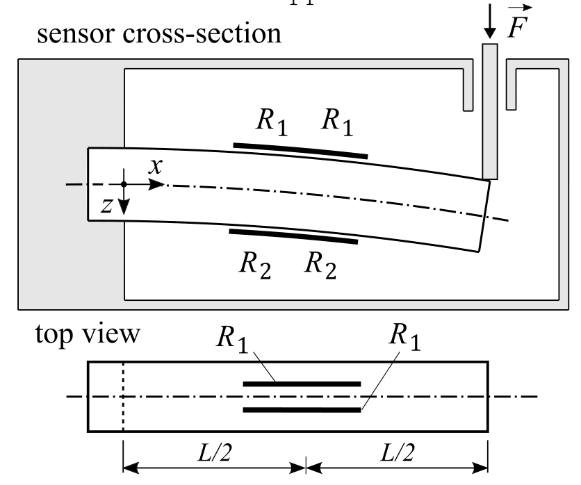
In what follows, assume that the deflection of the beam is very small.
i) The bending moment (i.e. the torque with which one fictitious half of the beam affects the other) is inversely proportional to the curvature radius of the center line of the beam: , where is Young’s modulus and is a constant depending on the geometry of the of the beam’s cross-section (both are known). Find the elongation of the upper wire when a force is applied to the sensor. Assume that the wires are placed in the middle of the beam. [2 т.]
ii) Find the resistances and when from the previous section is known and the initial resistance of the wires is . Assume that the volume of the wire remains constant during the deformation. [1 т.]
iii) The resistors are arranged in a Wheatstone bridge configuration shown in the figure below, where is the known battery voltage. Find the relationship between the measured voltage and the force .
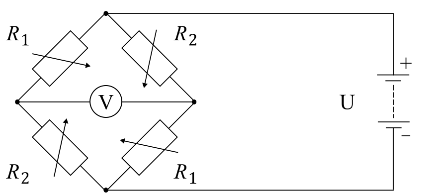
[2 т.]
Решение
— Solution by Päivo Simson, grading schemes by ....
i) (2 т.)
To find the elongation , we need to know the curvature radius of the beam at . The torque created by the force at an arbitrary point is . This must be balanced by the bending moment of the beam. In the middle of the beam we have
It is easy to see that if the upper wires elongate by , the lower ones shorten by the same amount. Now we need to relate the curvature radius with the elongation .
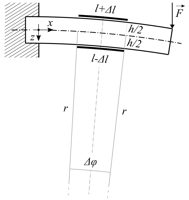
The arc length of a circle is . Knowing this, we have from the above figure
By dividing the above equations, we get an equation for that is easily solved:
Combining this with the expression for we have
Grading:
- Correct moment equation at the center of the beam (0.6 pts)
- Correct geometric relations for based on (0.6 pts)
- correctly solving for (0.6 pts)
- correctly expressing the final answer (0.2 pts)
ii) (1 т.)
Let and be the resistivity and the cross-sectional area of the wires, respectively. The initial resistance of all the wires is
where is the volume of the wire that remains constant during the deformation. Assuming we have
where
Grading:
- (0.3 pts)
- Correct approximations (0.3 pts)
- Correctly calculating the resistances and the change in resistance using the above relations (0.4 pts)
iii) (2 т.)
The total resistance of the circuit is
Since both sides of the circuit have the same total resistance , the current is also the same. The voltmeter reading is therefore
From this, we finally have
Grading:
- Correct total resistance of the Wheatstone circuit (0.5 pts)
- Assumes that the resistance of the Voltmeter is infinite (0.5 pts)
- Correctly calculating the potential difference as a function of the change in the resistance (0.5 pts)
- Expressing the final answer in the form given in the solution (0.5 pts)
Оригинал в Архива: NBPhO_2023_problems.pdf · официални решения: NBPhO_2023_solutions.pdf