Theoretical 2: Physics of the Oil and Gas Production
Условие
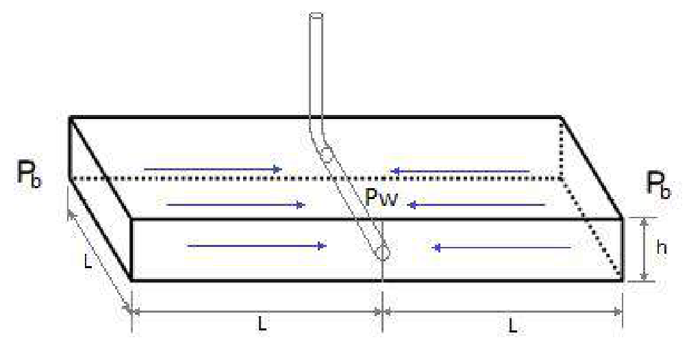
In this part the depletion process will be analyzed for the reservoir shown in Figure 8. The well has a horizontal part, therefore, the fluid flow in the reservoir is linear (h≪L).
Figure 8: System used for modeling reservoir depletion
This time, pressure at the bottom of the well Pw is constant (hydrostatic column of oil). However, the pressure at the boundary Pb(t) is changing with time, as well as the oil production rate q(t). In this model the flow rate of the fluid is given by:
q=−2φL2crhdtdPˉ,(5)
where cr is the compressibility of the rock, and the average pressure inside the reservoir Pˉ is approximated by:
Pˉ≈2Pb+Pw.(6)
(a) Derive an explicit expression for q(t) in terms of k,μ,cr,φ and reservoir dimensions, if the initial flow rate is q0. [1,2 т.]
(b) For the system described in this section, determine the time needed to deplete the oil reservoir by a half. [1 т.]
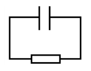
(c) Historically, first attempts to predict reservoir performance were made by doing analogies to electric circuits. Draw a simple electric circuit, which is analogous to the system described in Part 3. [0,5 т.]
(d) The reason why gas reservoirs cannot be modeled with the circuit as in 3.c, is that gas is highly compressible, with a compressibility being strongly dependent on the applied pressure. Compressibility is defined as:
c=−V1(dPdV)T,(7)
where V is initial volume of the examined sample, dV is isothermal volume change, when additional pressure dP is applied.
Assuming natural gas as ideal, derive its compressibility cg as function of pressure P. [0,3 т.]
Отговори
(a)q(t)=q0exp(−μL2crφ2kt)
(b)T=2kμL2crφln(1−μcrq02kh1)
(c) A circuit with a capacitor and a resistor (RC circuit).
From the problem statement, volume of oil produced is a half of the initial reserves:
Vproduced=21Vresφ=21(2L2h)φ(3.3.3)
Thus
T=2kμL2crφln(1−μcrq02kh1)(3.3.4)
Equation (3.3.4) gives rather bad results for real data, because the fluid flow model was very rough, nevertheless order of the magnitude usually is very close to the results from numerical simulations.
3.4 Equation for the flow rate q(t) derived in the part 3.2 is an exponential decline. Similar equation could be obtained for the circuit with a capacitor and a resistor. There a flow rate is analogous to the charge at the capacitor plate and term with compressibility is analogous to the resistor.
3.5 Ideal gas law:
V=PϑRT(3.5.1)
Differentiating Eq. (3.5.1)
(dPdV)T=−p21ϑRT(3.5.2)
Using definition of the compressibility and Eq. (3.5.2) results in
cg=−V1(dPdV)T=p1(3.5.3)
As it is seen with higher pressure gas behaves more like a fluid, with negligible compressibility. However during production, when pressure drops significantly, gas production deviates from exponential decline.