IPhO 1994, Експеримент — Задача 1. Determination of light reflectivity of a transparent dielectric surface
XXV International Physics Olympiad — Beijing, People’s Republic of China — Practical competition, July15,1994 · 15 юли 1994 г. · 10 т.
Внимание: Бележка към темата
The complete archived booklet contains two whole experiments, including Black Box, which the archive task listing omits. Experiments are shown here using original pages22–36. The round total20 is the sum of the native10-point marking schemes. Archived worked solutions have no established official authorship. Native differences/errors are retained: polarizerA/P1 labels, the linearity prose ratio versus the displayed formula, differing Brewster-angle uncertainties, low-frequency impedance/inductance wording, high-frequency Z_L approximately0 statement and original uncertainty values. Referenced separate oscilloscope/frequency-generator panel illustrations and plotting papers are absent from the obtained booklet; no missing illustrations or measurements are invented.
Practical competition — July15,1994 — Time available:2.5hours
- Use only the ball pen provided.
- Your graphs should be drawn on the answer sheets attached to the problem.
- Write your solution on the marked side of the paper only.
- The draft papers are provided for doing numerical calculations and draft drawings.
- Write at the top of every page:
- The number of the problem
- The number of the page of your report in each problem
- The total number of pages in your report to the problem
- Your name and code number
Условие
Experimental Apparatus
- He-Ne Laser (). The light from this laser is not linearly polarized.
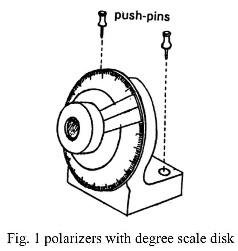
- Two polarizers (, ) with degree scale disk (Fig. 1), one () has been mounted in front of the laser output window as a polarizer, and another one can be fixed in a proper place of the drawing board by push-pins when it is necessary.
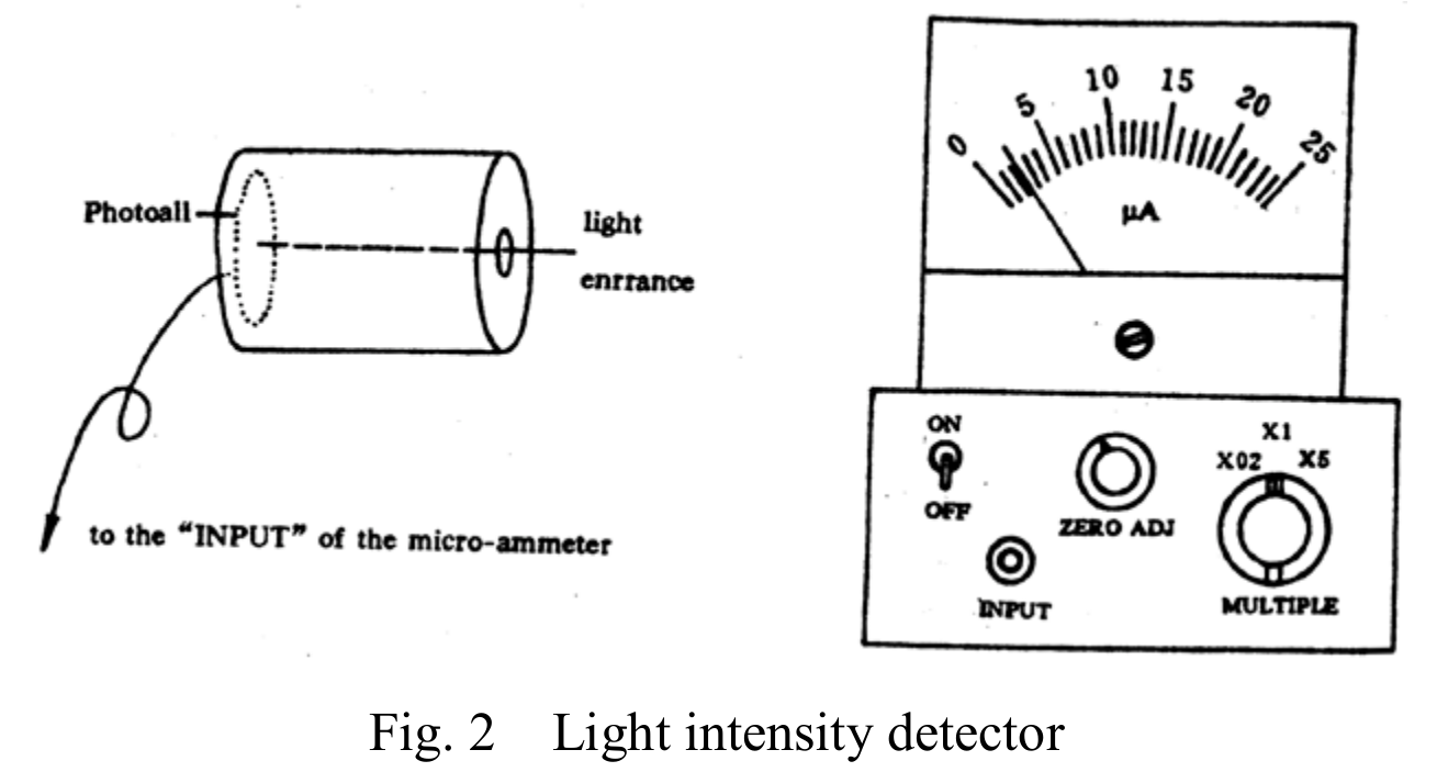
- Two light intensity detectors (, ) which consisted of a photocell and a microammeter (Fig. 2).
- Glass beam splitter (B).
- Transparent dielectric plate, whose reflectivity and refractive index are to be determined.
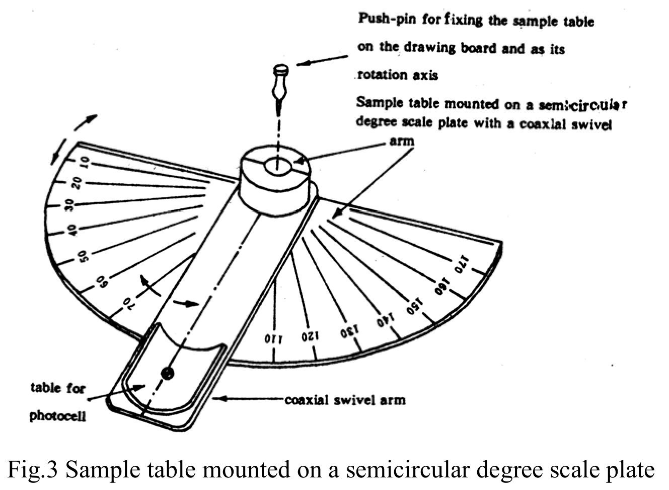
- Sample table mounted on a semicircular degree scale plate with a coaxial swivel arm (Fig. 3).
- Several push-pins for fixing the sample table on the drawing board and as its rotation axis.
- Slit aperture and viewing screen for adjusting the laser beam in the horizontal direction and for alignment of optical elements.
- Lute for adhere of optical elements in a fixed place.
- Wooden drawing board.
- Plotting papers.
Experiment Requirement
Determine the reflectivity of the -component as a function of the incident angle (the electric field component, parallel to the plane of incidence is called the -component).
1(a) Specify the transmission axis of the polarizer (A) by the position of the marked line on the degree scale disk in the -component measurement (the transmission axis is the direction of vibration of the electric field vector of the transmitted light). [1 т.]
1(b) Choose any one of the light intensity detector and set its micro-ammeter at the range of “×5”. Verify the linear relation ship between the light intensity and the micro-ammeter reading. Draw the optical schematic diagram. Show your measured data and calculated results (including the calculation formula) in the form of a table. Plot the linear relationship curve. [2 т.]
1(c) Determine the reflectivity of the -component as a function of the incident angle. Draw the optical schematic diagram. Show your measured data and calculated reflectivity (including the calculation formula) in the form of a table. Plot the reflectivity as a function of the incident angle. [4 т.]
2) Determine the refractive index of the sample as accurate as possible. [3 т.]
Explanation and Suggestion
- Laser radiation avoid direct eye exposure.
- Since the output power of the laser beam may fluctuate from time to time, the fluctuation of light output has to be monitored during the performance of the experiment and a correction of the experimental results has to be made.
- The laser should be lighting all the time, even when you finish your experiment and leave the examination hall, the laser should be keeping in work.
- The reflected light is totally plane polarized at an incident angle while
- Insert the plug of photocell into the “INPUT” socket of microammeter.
- Switching on the microammeter.
- Blocd off the light entrance hole in front of the photocell and adjust the scale reading of micro ammeter to “0”.
- Set the “Multiple” knob to a proper range.
Решение
1(a)
Determine the transmission axis of the polarizer and the Brewster angle of the sample by using the fact that the reflectivity of the -component at the Brewster angle.
Change the orientation of the transmission axis of , specified by the position of the marked line on the degree scale disk and the incident angle successively until the related intensity .
Now the incident light consists of -component only and the incident angle is , the corresponding values and are shown below:
The Brewster angle is .
1(b) — Verification of the linear relationship between the light intensity and the microammeter reading
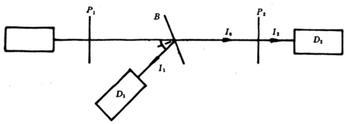
The intensity the transmitted light passing through two polarized and obeys Malus’ law
where is the intensity of the light polarized by and incident, is the intensity of the transmitted light, and is the angle between the transmission axes of and . Thus we can obtain light with various intensities for the verification by using two polarizers.
The experimental arrangement is shown in the figure.
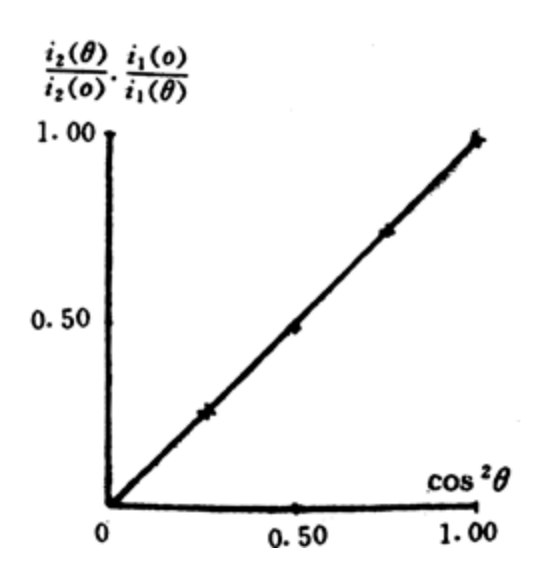
The light intensity detector serves to monitor the intensity fluctuation of the incident beam (the ratio of to remain unchanged), and measures . Let and be the readings of and respectively, and be the reading of the marked line position. when , the corresponding is , and the value of corresponding to is
Data and results;
| , | |||||
| , |
From the above data we can obtain the values of from the formula
and compare them with for examining the linear relationship. The results obtained are:
1(c) — Reflectivity measurement
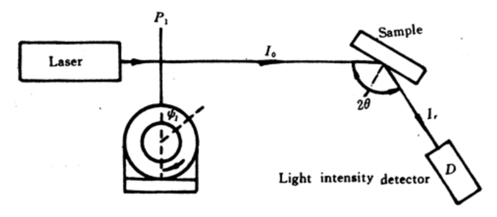
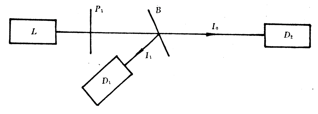
The experimental arrangement shown below is used to determine the ratio of to , which is proportional to the ratio of the reading of to the corresponding reading of .
Then used the experimental arrangement shown below to measure the relativity of the sample at various incident angle while the incident light consists of -component only. Let and be the readings of and respectively.
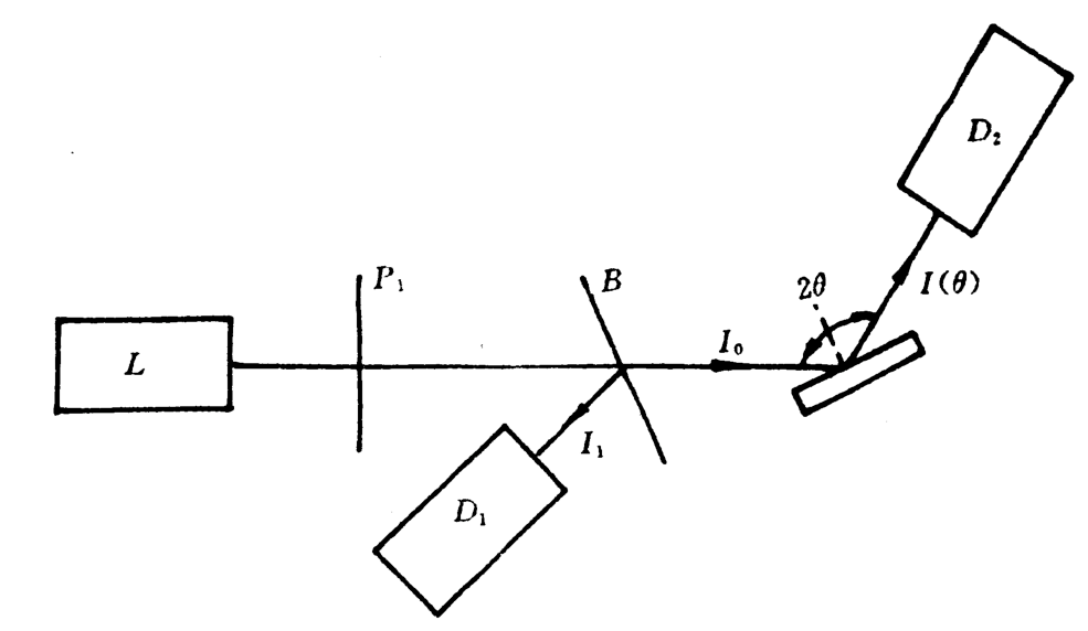
Then the reflectivity is
Data and results:
| () | () | ||
|---|---|---|---|
| 5 | 11.1 | 0.037 | |
| 10 | 11.2 | 0.036 | |
| 20 | 11.1 | 0.032 | |
| 30 | 12.2 | 0.025 | |
| 40 | 14.7 | 0.014 | |
| 50 | 16.9 | 0.0037 | |
| 53 | 11.3 | 0.0017 | |
| 55 | 11.3 | 0.00059 | |
| 56.3 (dark) | 11.5 | ||
| 58 | 11.5 | 0.0007 | |
| 60 | 13.5 | 0.0024 | |
| 64 | 16.7 | 0.011 | |
| 66 | 11.8 | 0.018 | |
| 68 | 15.0 | 0.029 | |
| 72 | 11.7 | 0.061 | |
| 76 | 14.0 | 0.13 | |
| 80 | 11.7 | 0.25 | |
| 84 | 14.5 | 0.42 |
The curve of reflectivity of -component as a function of incident in plexiglass
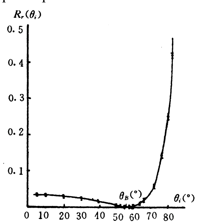
2)
The Brewster angle can be found from the above date as
The index of refraction can be calculated as
The sources of errors are:
- Detector sensitivity is low.
- The incident light does not consist of -component only.
- The degree scales are not uniform.
Grading Scheme (10 points)
Part 1. Reflectivity of the -component. 7 points, distributed as follows.
a. Determination of the transmission axis of the polarizer (A) in -component measurement, 1 point.
| Error | Points |
|---|---|
| less than | 1.0 |
| less than | 0.7 |
| less than | 0.3 |
| less than | 0.1 |
b. Verification of the linearity of the light intensity detector (2 points). Draws the optical schematic diagram correctly, 1.0 point; (Without the correction of the fluctuation of the light intensity, 0.4 point only);
Uses figure to show the “linearity”, 0.5 point;
Tabulate the measured data (with 5 points at least) correctly, 0.5 point.
c. Determination of the reflectivity of the -component of the light as a function of incident angle, 4 points, distributed as follows.
Draws the optical schematic diagram correctly and tabulate the measured data perfectly, 2.0 points;
Plot the reflectivity as the function of incident angle with indication of errors, 2 points.
Part 2. Determination of the refractive index of sample, 3 point.
Brewster angle of sample, 1 point;
| Error | Points |
|---|---|
| less than | 1.0 |
| less than | 0.5 |
| less than | 0.2 |
| larger than | 0 |
The refractive index of sample, 0.5 point.
Discussion and determination of errors, 1.5 points.
Оригинал в Архива: ipho94.pdf · решение от архива: ipho94.pdf